
Doepfer A-142-2 Envelope Controlled VCA
$289.00
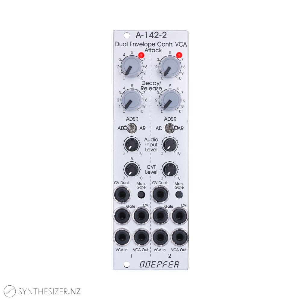
Module A-142-2 contains two envelope controlled VCAs behind a front panel with 8 HP only. Each of the two sub-units is the combination of a simple AD/ADSR/AR envelope generator and a VCA. The envelope generators have exponential curve shapes (charge/discharge curves of a capacitor). The VCAs have linear control scales.
The type of envelope can be selected by means of a toggle switch:
AD: Attack-Decay
AR: Attack-Release
ADSR: Attack-Decay-Sustain-Release with the limitation that Decay Time = Release Time and fixed Sustain level (factory setting 50%)
Each sub-unit provides these controls and in/outputs:
LED control (envelope display)
Attack (A), manual control
Decay/Release (D/R), manual control
Mode switch (AD, AR, ADSR)
Audio level control (small control without knob)
CVT Input (CVT = CV Time)
CV Ducking input
Attenuator for CVT (small control without knob)
Gate Input (min. +5V, max. +12V)
Manual Gate (momentary switch)
Audio Input
Audio Output
Envelope Output The Envelope Output of version 1 has been cancelled for the benefit of the new CV Duck input. But there is an internal pin header available that has available the envelope signal (0...+10V) and the CV input of the VCA (0...+10V). Ex works the pins are shortened by a jumper but can be used for modifications (envelope output, VCA CV input).
By means of two internal jumpers for each sub-unit one can select which parameter(s) are controlled by the CVT input (e.g. D/R only or A only or A and D/R) and in which direction (i.e. if an increasing CVT shortens or stretches the time parameter in question).
Two more jumpers are used for the optional bus access to the gate signal of the bus for each envelope.
Another jumper enables the Gate normalling of the two units, i.e. Gate socket of unit 1 is normalled to the Gate socket of unit 2. That way only one Gate signal is used to trigger both units.
CV Duck is an additional control input for the VCA that can be used to mute the VCA by means of an external control voltage. Beyond about +5V CV Duck the VCA is fully muted, in the range 0...+5V there is only a partial muting. Circuitry-wise the CV Duck signal is amplified by two, inverted and added to the internal envelope signal (0...+10V). The sum of both signals is used to control the VCA.
The time range of Attack/Decay/Release is about 1ms to 30s (can be modified by changing the value of a capacitor).
Applications:
Virtually in each patch one or more envelope/VCA combos together with a sound source are very useful, mainly for percussive sounds.
Voltage control of the times and the ducking animates each performance.
Additional technical information:
The voltage level of the used gate signal has to be at least +5V and the rising/falling slopes has to be fast enough. Otherwise the envelope will be not work in the right way. We discovered that some modules from other manufacturers do not meet these specifications. In this case the level shifter module A-183-4 may help by connecting one unit of the the module between the gate source and the gate input of the A-142-2.
Out of stock
- Manufacturer's warranty
- Pre-orders ship 1-2 days after arrival in NZ
- Free NZ/AU shipping on all orders over NZ$399
- Free worldwide shipping on all orders over USD$499
Manufacturer Doepfer
Status Pre-order
Functionality
Envelope Generator